December 26, 2012

Quick Sort

 
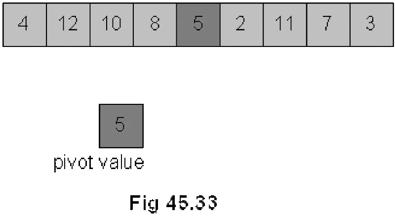
Quicksort is another divide and conquer algorithm. Quicksort is based on the idea of partitioning (splitting) the list around a pivot or split value. Quicksort is also a divide and conquer algorithm. We see pictorially, how the quick sort algorithm works. Suppose we have an array as shown in the figure Fig 45.33.
clip_image002
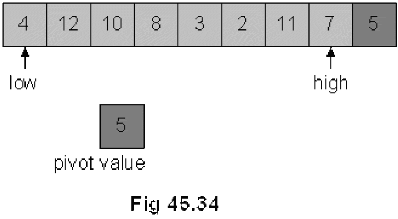
We select an element from the array and call it the pivot. In this array, the pivot is the middle element 5 of the array. Now, we swap this with the last element 3 of the array. The updated figure of the array is shown in Fig 45.34.
clip_image004
As shown in Fig 45.34, we used two indexes low and high. The index low is started from 0th position of the array and goes towards right until n-1th position. Inside this loop, an element that is bigger than the pivot is searched. The low index is incremented further as 4 is less than 5.
clip_image006
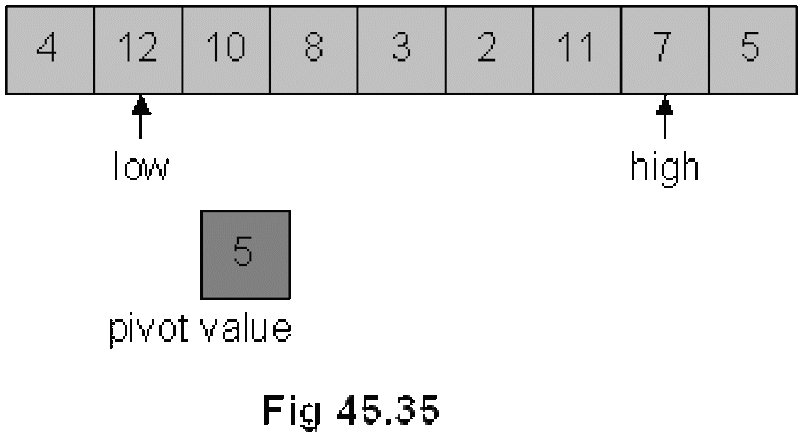
low is pointing to element 12 and it is stopped here as 12 is greater than 5. Now, we start from the other end, the high index is moved towards left from n-1th position to 0. While coming from right to left, we search such an element that is smaller than 5. Elements 7 and 11 towards left are greater than 5, therefore, the high pointer is advanced further towards left. high index is stopped at the next position as next element 2 is smaller than 5. Following figure Fig 45.36 depicts the latest situation.

Divide and Conquer

We had started discussing three new sorting algorithms; merge sort, quick sort and heap sort. All of these three algorithms take time proportional to nlog2n. Our elementary three sorting algorithms were taking n2 time; therefore, these new algorithms with nlog2n time are faster. In search operation, we were trying to reduce the time from n to log2n.
Let’s discuss these sorting algorithms; merge sort, quick sort and heap sort in detail.
We had started our discussion from divide and conquer rule where we also saw an example. Instead of sorting a whole array, we will divide it in two parts, each part is sorted separately and then they are merged into a single array.
clip_image002
Let’ see few analysis to confirm the usefulness of the divide and conquer technique.
- To sort the halves approximate time is (n/2)2+(n/2)2
- To merge the two halves approximate time is n
- So, for n=100, divide and conquer takes approximately:
= (100/2)2 + (100/2)2 + 100
= 2500 + 2500 + 100
= 5100 (n2 = 10,000)

Comparison of Complexity of Algorithms

We have studied these three algorithms i.e. selection sort, insertion sort and bubble sort. Now considering the above three algorithms, we see that these algorithms are easy to understand. Coding for these algorithms is also easy. These three algorithms are in place algorithms. There is no need of extra storage for sorting an array by these algorithms. With respect to the time complexity, these algorithms are proportional to N2. Here N is the number of elements. So we can see that as the value of N increases, the performance time of these algorithms increases considerably as it is proportional to N2. Thus these algorithms are expensive with respect to time performance. There are algorithms that have the time complexity proportional to N log2 (N). The following table shows the respective values of N2 and N log2(N) for some values of N.

N N2 N Log2 (N)
10 100 33.21
100 10000 664.38
1000 1000000 9965.78
10000 100000000 132877.12
100000 10000000000 1660964.04
1000000 1E+12 19931568.57

From this table we can see that for a particular value of N, the value of N2 is very large as compared to the value of N log2 (N). Thus we see that the algorithms whose time complexity is proportional to N2 are much time consuming as compared to the algorithms the time complexity of which is proportional to N log2 (N). Thus we see that the N log2 (N) algorithms are better than the N2 algorithms.

N log2 (N) Algorithms
Now let’s see the algorithms that are N log2 (N) algorithms. These include the following algorithms.
  • Merge Sort
  • Quick Sort
  • Heap Sort
These three algorithms fall under ‘divide and conquer category’. The divide and conquer strategy is well known in wars. The philosophy of this strategy is ,’ divide your enemy into parts and then conquer these parts’. To conquer these parts is easy, as these parts cannot resist or react like a big united enemy. The same philosophy is applied in the above algorithms. To understand the divide and conquer strategy in sorting algorithm, let’s consider an example. Suppose we have an unsorted array of numbers is given below.

Bubble Sort

The third sorting algorithm is bubble sort. The basic idea of this algorithm is that we bring the smaller elements upward in the array step by step and as a result, the larger elements go downward. If we think about array as a vertical one, we do bubble sort. The smaller elements come upward and the larger elements go downward in the array. Thus it seems a bubbling phenomenon. Due to this bubbling nature, this is called the bubble sort. Thus the basic idea is that the lighter bubbles (smaller numbers) rise to the top. This is for the sorting in ascending order. We can do this in the reverse order for the descending order.
The steps in the bubble sort can be described as below
• Exchange neighboring items until the largest item reaches the end of the array
• Repeat the above step for the rest of the array
In this sort algorithm, we do not search the array for the smallest number like in the other two algorithms. Also we do not insert the element by shifting the other elements. In this algorithm, we do pair-wise swapping. We will take first the elements and swap the smaller with the larger number. Then we do the swap between the next pair. By repeating this process, the larger number will be going to the end of the array and smaller elements come to the start of the array.

Insertion Sort

The main idea of insertion sort is
• Start by considering the first two elements of the array data. If found out of order, swap them
• Consider the third element; insert it into the proper position among the first three elements.
• Consider the fourth element; insert it into the proper position among the first four elements.
• … …
This algorithm is not something uncommon to the persons who know card playing. In the game of cards, a player gets 13 cards. He keeps them in the sorted order in his hand for his ease. A player looks at the first two cards, sorts them and keeps the smaller card first and then the second. Suppose that two cards were 9 and 8, the player swap them and keep 8 before 9. Now he takes the third card. Suppose, it is 10, then it is in its position. If this card is of number 2, the player will pick it up and put it on the start of the cards. Then he looks at the fourth card and inserts it in the first three cards (that he has sorted) at a proper place. He repeats the same process with all the cards and finally gets the cards in a sorted order. Thus in this algorithm, we keep the left part of the array sorted and take element from the right and insert it in the left part at its proper place. Due to this process of insertion, it is called insertion sorting.

Selection Sort

 
Suppose we have an array with different numbers. For sorting it in an ascending order, selection sorting will be applied on it in the following manner. We find the smallest number in the array and bring it to the position 1. We do the same process with the remaining part of the array and bring the smallest number among the remaining array to the next position. This process continues till the time all the positions of the array are filled with the elements. Thus the main idea of selection sort is that
• find the smallest element
• put it in the first position
• find the next smallest element in the remaining elements
• put it in the second position
• …
• And so on, until we get to the end of the array
Let’s understand this algorithm by considering an example with the help of figures.
Consider an array that has four numbers i.e. 19, 5, 7 and 12 respectively. Now we want to sort this array in ascending order. To sort the array, selection algorithm will be applied on it.

Binary Search

 
The binary search is an algorithm of searching, used with the sorted data. As we have sorted elements in the array, binary search method can be employed to find data in the array. The binary search finds an element in the sorted array in log n time. If we have 100000 elements in the array, the log 1000000 will be 20 i.e. very small as compared to 100000. Thus binary search is very fast.
The binary search is like looking up a phone number in the directory or looking up a word in the dictionary. For looking a word in the dictionary, we start from the middle in the dictionary. If the word that we are looking for comes before words on the page, it shows that the word should be before this page. So we look in the first half. Otherwise, we search for the word in the second half of the dictionary. Suppose the word is in the first half of the dictionary, we consider first half for looking the word. We have no need to look into the second half of the dictionary. Thus the data to be searched becomes half in a step. Now we divide this portion into two halves and look for the word. Here we again come to know that the word is in the first half or in the second half of this portion. The same step is repeated with the part that contains the required word. Finally, we come to the page where the required word exists. We see that in the binary search, the data to be searched becomes half in each step. And we find the entry very fast. The number of maximum steps needed to find an entry is log n, where n is the total number of entries. Now if we have 100000 entries, the maximum number of attempts (steps) required to find out the entry will be 20 (i.e. log 1000000).
If already sorted data is available, then it is better to apply an algorithm of binary search for finding some item inside instead of searching from start to the end in sequence. The application of this algorithm will help get the results very quickly.

December 25, 2012

Traffic Flow on Nodes in NS2

In this tutorial, we are going to create some nodes and then enable the flow of traffic on those nodes. There are two ways to flow the traffic i.e. through TCP and UDP. We will use both in this tutorial.


#Create a simulator object
set ns [new Simulator]

#Define different colors for data flows (for NAM)
$ns color 1 Blue
$ns color 2 Red
$ns color 3 Black

#Open the NAM trace file
set nf [open out.nam w]
$ns namtrace-all $nf

#Define a 'finish' procedure
proc finish {} {
        global ns nf
        $ns flush-trace
        #Close the NAM trace file
        close $nf
        #Execute NAM on the trace file
        exec nam out.nam &
        exit 0
}

#Create four nodes
set n0 [$ns node]
set n1 [$ns node]
set n2 [$ns node]
set n3 [$ns node]

$n3 shape "square"
$n3 color "black"

$n0 shape "square"
$n0 color "blue"

#Create links between the nodes
$ns duplex-link $n0 $n2 2Mb 10ms DropTail
$ns duplex-link $n1 $n2 2Mb 10ms RED
$ns duplex-link $n2 $n3 1.7Mb 20ms RED

$ns duplex-link-op $n0 $n2 color "blue"
$ns duplex-link-op $n0 $n2 label "cs-study"

$ns duplex-link-op $n1 $n2 color "green"
$ns duplex-link-op $n1 $n2 label "easylearning"

#Set Queue Size of link (n2-n3) to 10
$ns queue-limit $n2 $n3 10

#Give node position (for NAM)
$ns duplex-link-op $n0 $n2 orient right-down
$ns duplex-link-op $n1 $n2 orient right-up
$ns duplex-link-op $n2 $n3 orient right

#Monitor the queue for link (n2-n3). (for NAM)
$ns duplex-link-op $n2 $n3 queuePos 0.5


#Setup a TCP connection
set tcp [new Agent/TCP]
$tcp set class_ 3
$ns attach-agent $n0 $tcp
set sink [new Agent/TCPSink]
$ns attach-agent $n3 $sink
$ns connect $tcp $sink
$tcp set fid_ 1

#Setup a FTP over TCP connection
set ftp [new Application/FTP]
$ftp attach-agent $tcp
$ftp set type_ FTP


#Setup a UDP connection
set udp [new Agent/UDP]
$ns attach-agent $n1 $udp
set null [new Agent/Null]
$ns attach-agent $n3 $null
$ns connect $udp $null
$udp set fid_ 2

#Setup a CBR over UDP connection
set cbr [new Application/Traffic/CBR]
$cbr attach-agent $udp
$cbr set type_ CBR
$cbr set packet_size_ 1000
$cbr set rate_ 1mb
$cbr set random_ false


#Schedule events for the CBR and FTP agents
$ns at 0.1 "$cbr start"
$ns at 1.0 "$ftp start"
$ns at 4.0 "$ftp stop"
$ns at 4.5 "$cbr stop"

#Detach tcp and sink agents (not really necessary)
$ns at 4.5 "$ns detach-agent $n0 $tcp ; $ns detach-agent $n3 $sink"

#Call the finish procedure after 5 seconds of simulation time
$ns at 5.0 "finish"

#Print CBR packet size and interval
puts "CBR packet size = [$cbr set packet_size_]"
puts "CBR interval = [$cbr set interval_]"

#Run the simulation
$ns run


The output of the above code is as follows. Run the program by typing ‘ns trafficflow.tcl’ in terminal.


After it gets executed, the following output is displayed in nam.


Now, click on the Play button which is underlined green.


We can see the traffic flow as well as the traffic which are being dropped on node 2 because the limits of the node to hold the packets is limited. Thats why when the queue is full and there is no more capacity available, the packet drops.


The little bars below the link between node 2 and node 3 indicates the acknowledgement that is being sent from node 3 to node 0 because it is using TCP.
 

Code Explained:

set ns [new Simulator]: generates an NS simulator object instance, and assigns it to variable ns. 


The "Simulator" object has member functions that do the following:

    • Create compound objects such as nodes and links (described later)
    • Connect network component objects created (ex. attach-agent)
    • Set network component parameters (mostly for compound objects)
    • Create connections between agents (ex. make connection between a "tcp" and "sink")
    • Specify NAM display options


Most of member functions are for simulation setup (referred to as plumbing functions in the Overview section) and scheduling, however some of them are for the NAM display. The "Simulator" object member function implementations are located in the "ns-2/tcl/lib/ns-lib.tcl" file.

  • $ns color fid color: is to set color of the packets for a flow specified by the flow id (fid). This member function of "Simulator" object is for the NAM display, and has no effect on the actual simulation.


  • $ns namtrace-all file-descriptor: This member function tells the simulator to record simulation traces in NAM input format. It also gives the file name that the trace will be written to later by the command $ns flush-trace. Similarly, the member function trace-all is for recording the simulation trace in a general format.


  • proc finish {}: is called after this simulation is over by the command $ns at 5.0 "finish". In this function, post-simulation processes are specified.


  • set n0 [$ns node]: The member function node creates a node. A node in NS is compound object made of address and port classifiers (described in a later section). Users can create a node by separately creating an address and a port classifier objects and connecting them together. However, this member function of Simulator object makes the job easier. To see how a node is created, look at the files: "ns-2/tcl/libs/ns-lib.tcl" and "ns-2/tcl/libs/ns-node.tcl".


  • $ns duplex-link node1 node2 bandwidth delay queue-type: creates two simplex links of specified bandwidth and delay, and connects the two specified nodes. In NS, the output queue of a node is implemented as a part of a link, therefore users should specify the queue-type when creating links. In the above simulation script, DropTail queue is used. If the reader wants to use a RED queue, simply replace the word DropTail with RED. The NS implementation of a link is shown in a later section. Like a node, a link is a compound object, and users can create its sub-objects and connect them and the nodes. Link source codes can be found in "ns-2/tcl/libs/ns-lib.tcl" and "ns-2/tcl/libs/ns-link.tcl" files. One thing to note is that you can insert error modules in a link component to simulate a lossy link (actually users can make and insert any network objects). Refer to the NS documentation to find out how to do this.


  • $ns queue-limit node1 node2 number: This line sets the queue limit of the two simplex links that connect node1 and node2 to the number specified. At this point, the authors do not know how many of these kinds of member functions of Simulator objects are available and what they are. Please take a look at "ns-2/tcl/libs/ns-lib.tcl" and "ns-2/tcl/libs/ns-link.tcl", or NS documentation for more information.


  • $ns duplex-link-op node1 node2 ..: The next couple of lines are used for the NAM display. To see the effects of these lines, users can comment these lines out and try the simulation.

Now that the basic network setup is done, the next thing to do is to setup traffic agents such as TCP and UDP, traffic sources such as FTP and CBR, and attach them to nodes and agents respectively.


  • set tcp [new Agent/TCP]: This line shows how to create a TCP agent. But in general, users can create any agent or traffic sources in this way. Agents and traffic sources are in fact basic objects (not compound objects), mostly implemented in C++ and linked to OTcl. Therefore, there are no specific Simulator object member functions that create these object instances. To create agents or traffic sources, a user should know the class names these objects (Agent/TCP, Agnet/TCPSink, Application/FTP and so on). This information can be found in the NS documentation or partly in this documentation. But one shortcut is to look at the "ns-2/tcl/libs/ns-default.tcl" file. This file contains the default configurable parameter value settings for available network objects. Therefore, it works as a good indicator of what kind of network objects are available in NS and what are the configurable parameters.


  • $ns attach-agent node agent: The attach-agent member function attaches an agent object created to a node object. Actually, what this function does is call the attach member function of specified node, which attaches the given agent to itself. Therefore, a user can do the same thing by, for example, $n0 attach $tcp. Similarly, each agent object has a member function attach-agent that attaches a traffic source object to itself.


  • $ns connect agent1 agent2: After two agents that will communicate with each other are created, the next thing is to establish a logical network connection between them. This line establishes a network connection by setting the destination address to each others' network and port address pair.


Assuming that all the network configuration is done, the next thing to do is write a simulation scenario (i.e. simulation scheduling). The Simulator object has many scheduling member functions. However, the one that is mostly used is the following:

  • $ns at time "string": This member function of a Simulator object makes the scheduler (scheduler_ is the variable that points the scheduler object created by [new Scheduler] command at the beginning of the script) to schedule the execution of the specified string at given simulation time. For example, $ns at 0.1 "$cbr start" will make the scheduler call a start member function of the CBR traffic source object, which starts the CBR to transmit data. In NS, usually a traffic source does not transmit actual data, but it notifies the underlying agent that it has some amount of data to transmit, and the agent, just knowing how much of the data to transfer, creates packets and sends them.

After all network configuration, scheduling and post-simulation procedure specifications are done, the only thing left is to run the simulation. This is done by $ns run.


Nodes creation in NS2


Add the following code to the new file and named it with the extension of tcl. i.e. filename.tcl . To create the file go to the terminal.
Write
gedit filename.tcl

This above command will open a file with the name filename.tcl. Add the following code to the file and save the file.

Now, in order  to run the file go to the Terminal and write the following command.

ns filename.tcl


Code:


#Create a simulator object
set ns [new Simulator]


#Open the NAM trace file

set nf [open o.nam w]
$ns namtrace-all $nf

# create nodes

set n0 [$ns node]
set n1 [$ns node]
set n2 [$ns node]
set n3 [$ns node]
set n4 [$ns node]
set n5 [$ns node]
set n7 [$ns node]
set n8 [$ns node]
set n10 [$ns node]

December 19, 2012

NS2 and UBUNTU Installation on VMWARE

There are multiple ways that you can adopt to install ns2. As ns2 runs on the linux. so first you will have to install linux. You can install any distribution of linux fedora, ubuntu etc.

So, one way to do the installation is to first install this software called VMWARE. It creates a virtual machine which allows you to run operating system on another operating system just like any other application. Other ways include by installing Ubuntu direct from website using windows installer. Lets look at the first option.
So,

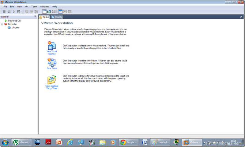
Install Vmware

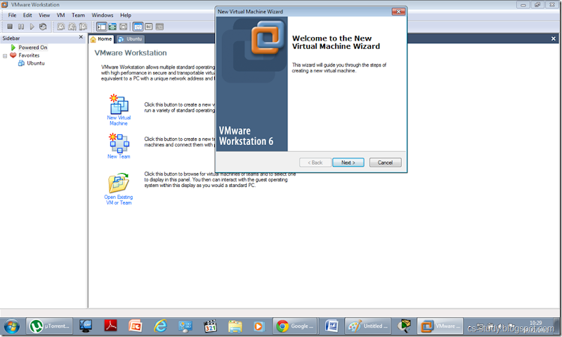
Install fedora or any other Linux distribution on VMware. Select ‘New Virtual Machine’ option.

2

Click Next.
 3


December 10, 2012

Voice over IP (VOIP) on packet tracer

Voice over IP (VoIP, or voice over Internet Protocol) commonly refers to the communication protocols, technologies, methodologies, and transmission techniques involved in the delivery of voice communications and multimedia sessions over Internet Protocol (IP) networks, such as the Internet. Other terms commonly associated with VoIP are IP telephony,Internet telephony, voice over broadband (VoBB), broadband telephony, IP communications, and broadband phone.
Internet telephony refers to communications services —voice, fax, SMS, and/or voice-messaging applications— that are transported via the Internet, rather than the public switched telephone network (PSTN). The steps involved in originating a VoIP telephone call are signaling and media channel setup, digitization of the analog voice signal, encoding, packetization, and transmission as Internet Protocol (IP) packets over a packet-switched network. On the receiving side, similar steps (usually in the reverse order) such as reception of the IP packets, decoding of the packets and digital-to-analog conversion reproduce the original voice stream. Even though IP telephony and VoIP are used interchangeably, IP telephony refers to all use of IP protocols for voice communication by digital telephony systems, while VoIP is one technology used by IP telephony to transport phone calls

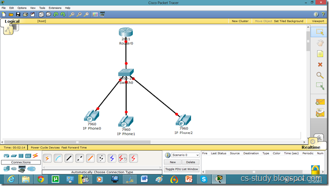
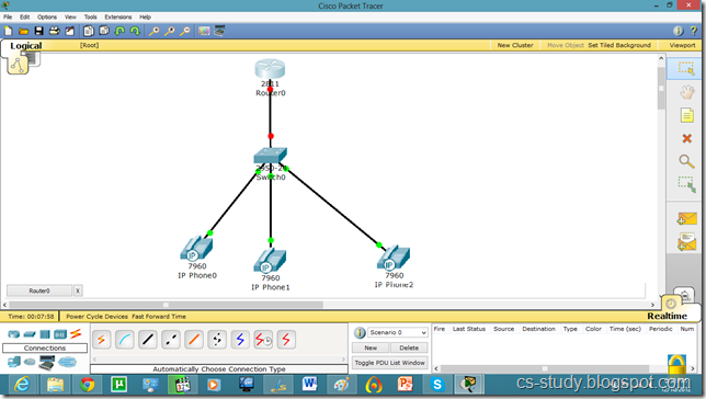
Let us apply it on packet tracer.
1

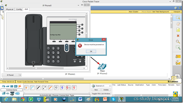
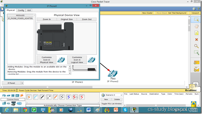
This IP Phone is displayed below. And when we try to go to any other mode its give us error and ask us to switch it on first.

 2
For that, go to Physical mode and put the power adapter (in the bottom right corner) into the phone as shown in figure.

 3
Now, we have inserted the antenna into IP phone. Repeat it for other phones as well.

 4
Now, we see that interface of IP phone is UP.

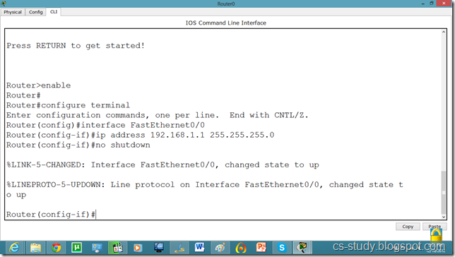
 5

Now, go to router and assign IP address.

 6

We will have to set DHCP server on router to assign IP addresses to IP phones.

 7
We will have to give an additional command for voip.
Router(dhcp-config)#option 150 ip 192.168.1.1

 8
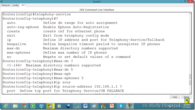
Now, let us apply commands to the router for voip. You might have noticed we took 2811 series router because it facilitates the following commands.

 9

Continued.
 10

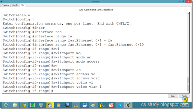
Now, we will go to the switch and make the interfaces support voip as follows.

 11

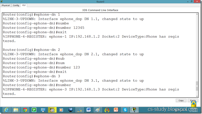
After that, we will have to assign phone number to our IP phone by applying following commands.
 12

Continued…

 13

Now, we can see that in GUI mode of Phone, we have a phone number available.

 14

This means that we can call from one phone to the other. Lets do that.

 15

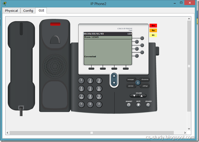
And when we pick up the reciever, it says that we are connected :) .

 16
 

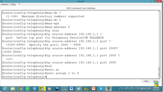
Commands on Router for VOIP

Router(config)#ip dhcp pool voice

Router(dhcp-config)#option 150 ip 192.168.1.1
Router(dhcp-config)#exit

Router(config)#telephony-service

Router(config-telephony)#max-dn 5

Router(config-telephony)#max-ephones 5

Router(config-telephony)#ip source-address 192.168.1.1 port 2000

Router(config-telephony)#auto assign 1 to 9
Router(config-telephony)#exit

Router(config)#ephone-dn 1
%LINK-3-UPDOWN: Interface ephone_dsp DN 1.1, changed state to up

Router(config-ephone-dn)#number 12345
Router(config-ephone-dn)#exit

%IPPHONE-6-REGISTER: ephone-1 IP:192.168.1.2 Socket:2 DeviceType:Phone has registered.
Router(config)#ephone-dn 2

%LINK-3-UPDOWN: Interface ephone_dsp DN 2.1, changed state to up

Router(config-ephone-dn)#number 123
Router(config-ephone-dn)#exit
Router(config)#ephone-dn 3
%LINK-3-UPDOWN: Interface ephone_dsp DN 3.1, changed state to up

Router(config-ephone-dn)#number 11111
Router(config-ephone-dn)#exit

Commands on Switch for VOIP
Switch(config)#interface range fastEthernet 0/1 - fastEthernet 0/10
Switch(config-if-range)#switchport mode access

Switch(config-if-range)#switchport voice vlan 1

December 9, 2012

Telnet and SSH on packet tracer

A terminal emulation program for TCP/IP networks such as the Internet. The Telnet program runs on your computer and connects your PC to a server on the network. You can then enter commands through the Telnet program and they will be executed as if you were entering them directly on the server console. This enables you to control the server and communicate with other servers on the network. To start a Telnet session, you must log in to a server by entering a valid username and password. Telnet is a common way to remotely control Web servers. To telnet means to establish a connection with the Telnet protocol, either with command line client or with a programmatic interface.
SSH 
Secure Shell (SSH) is a cryptographic network protocol for secure data communication, remote shell services or command execution and other secure network services between two networked computers that connects, via a secure channel over an insecure network, a server and a client (running SSH server and SSH client programs, respectively). It was designed as a replacement for Telnet and other insecure remote shell protocols such as the Berkeley rsh and rexec protocols, which send information, notably passwords, in plaintext, rendering them susceptible to interception and disclosure using packet analysis. The encryption used by SSH is intended to provide confidentiality and integrity of data over an unsecured network, such as the Internet.

a network protocol that ensures a high-level encryption, allowing for the data transmitted over insecure networks, such as the Internet, to be kept intact and integrate. SSH and SSH Telnet, in particular, work for establishing a secure communication between two network-connected computers as an alternative to remote shells, such as TELNET, that send sensitive information in an insecure environment. 

In contrast to other remote access protocols, such as FTP, SSH Telnet ensures higher level of connection security between distant machines but at the same time represents a potential threat to the server stability. Thus, SSH access is considered a special privilege by hosting providers and is often assigned to users only per request. 

Let us apply Telnet and SSH on packet tracer.

 1
Take the topology as in the above diagram. Set IPs on the PCs. As, by default, all PCs are in vlan 1. We will create a virtual interface on switch with vlan 1 as follows.

 2

Now, we can ping to switch by our hosts because hosts are in vlan 1 and switch also has a vlan 1 interface.
 3

Now, try to telnet the switch from our PC, it refuses because we have not applied authentication on the switch yet.
 4
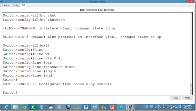
So, lets apply line authentication on the switch. The system supports 20 virtual tty (vty) lines for Telnet, Secure Shell Server (SSH) and FTP services. Each Telnet, SSH, or FTP session requires one vty line. You can add security to your system by configuring the software to validate login requests. 

 4.5
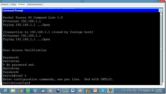
Now, we can easily telnet. But it does not let us go in the switch enabled mode because we have not set the password on the switch yet.

 5

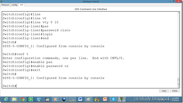
Lets apply password on the switch enabled mode.

 6
Now, we can go inside Switch configuration mode from our pc.

 7

So, now let us apply SSH on the switch.

 9

Commands continued.

 11

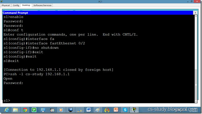
Now, we try to telnet it but it is refused because ssh has over ruled telnet. So, we will use SSH protocol on it. By default username is admin.

 12

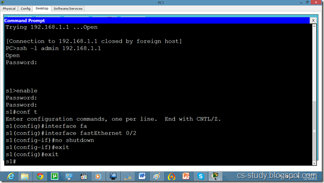
And we can apply any sort of configuration on our switch from out pc.

 13

Now, if we want to change the username from admin to something else, we will do it as follows.

14

and from our pc as follows.

15

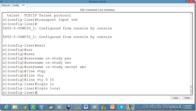
The SSH commands are as follows.

Switch(config)#ip domain name ?

 WORD  Default domain nameSwitch(config)#ip domain name abc.comSwitch(config)#crypto key generate rsa
% Please define a hostname other than Switch.


Switch(config)#hostname s1


s1(config)#ip domain name cs-studys1

s1(config)#crypto key generate rsa

Choose the size of the key modulus in the range of 360 to 2048 for your General Purpose Keys. Choosing a key modulus greater than 512 may take   a few minutes.

s1(config)#line vty 0 15

s1(config-line)#transport input ssh

The name for the keys will be: s1.cs-study
How many bits in the modulus [512]: 1024

% Generating 1024 bit RSA keys, keys will be non-exportable...[OK]

s1(config)#ip ssh version 2

s1(config-line)#

Password Authentication Protocol on packet tracer (PAP)

The Point-to-Point Protocol (PPP) is a data link protocol commonly used in establishing a direct connection between two networking nodes. It can provide connection authentication, transmission encryption and compression. PPP is used over many types of physical networks including serial cable, phone line,  trunk line, cellular telephone, specialized radio links, and fiber optic links etc. Internet service providers (ISPs) have used PPP for customer dial-up access to the Internet, since IP packets cannot be transmitted over a modem line on their own, without some data link protocol. PPP is commonly used as a data link layer protocol for connection over synchronous and asynchronous circuits, where it has largely superseded the older Serial Line Internet Protocol (SLIP) and telephone company mandated standards (such as Link Access Protocol, Balanced (LAPB).  
PPP was designed somewhat after the original HDLC specifications. The designers of PPP included many additional features that had been seen only in proprietary data-link protocols up to that time.
HDLC
HDLC provides both connection-oriented and connectionless service. HDLC can be used for point to multipoint connections, but is now used almost exclusively to connect one device to another, using what is known as Asynchronous Balanced Mode (ABM).
PAP
A password authentication protocol (PAP) is an authentication protocol that uses a password. PAP is used by Point to Point Protocol to validate users before allowing them access to server resources. Almost all network operating system remote servers support PAP.
PAP transmits unencrypted ASCII passwords over the network and is therefore considered insecure. It is used as a last resort when the remote server does not support a stronger authentication protocol, like CHAP or EAP (the latter is actually a framework).
Password-based authentication is the protocol that two entities share a password in advance and use the password as the basis of authentication. Existing password authentication schemes can be categorized into two types: weak-password authentication schemes and strong-password authentication schemes. In general, strong-password authentication protocols have the advantages over the weak-password authentication schemes in that their computational overhead are lighter, designs are simpler, and implementation are easier, and therefore are especially suitable for some constrained environments.

PAP works basically the same way as the normal login procedure. The client authenticates itself by sending a user name and an (optionally encrypted) password to the server, which the server compares to its secrets database. This technique is vulnerable to eavesdroppers who may try to obtain the password by listening in on the serial line, and to repeated trial and error attacks.

Let us apply PPP on packet tracer. Consider the following simpler topology.
 
1

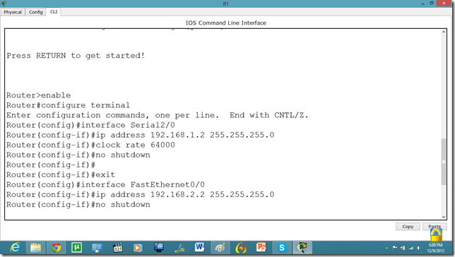
Let us apply IP addresses on the interfaces and change the state of the interface from down to UP. So that they can communicate.
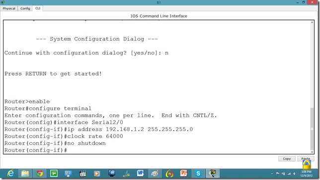
 2
Similarly, for serial interface.

 3
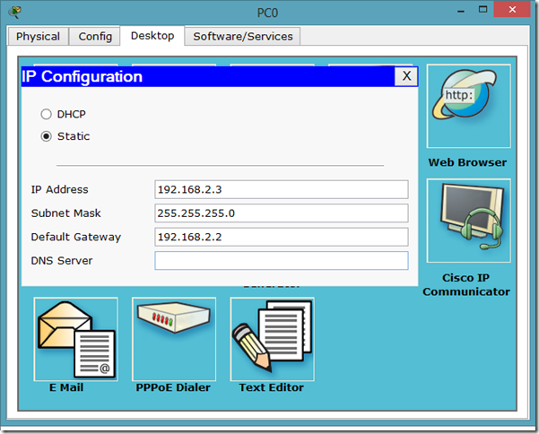
PC IP setup

 4

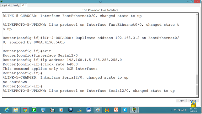
The IP configuration on other router.
 5

serial int setup.

 6
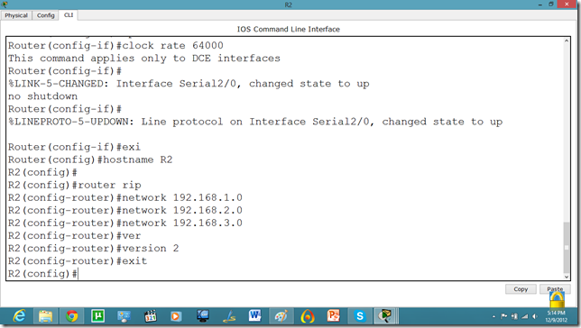
Now, we know that PCs that are attached cannot communicate until we apply a routing mechanism. In this case we are applying the RIP V2 protocol. Apply the following set of commands on both routers. We have also set the hostname of the router which will be useful to us later.
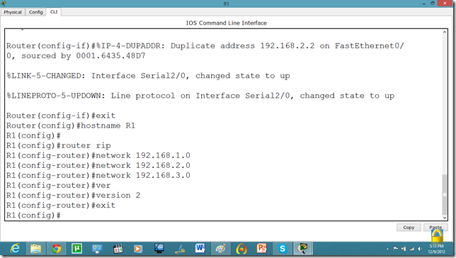
 7
Now, let us set the commands on the second router as well.
 8

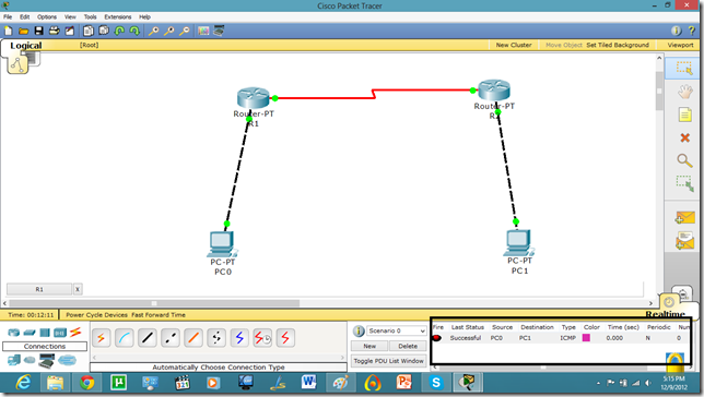
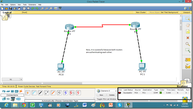
Now, both PCs can communicate.
 9

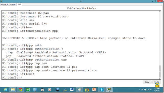
Now, we will set the authentication, In this tutorial we are going to apply PAP.
 11

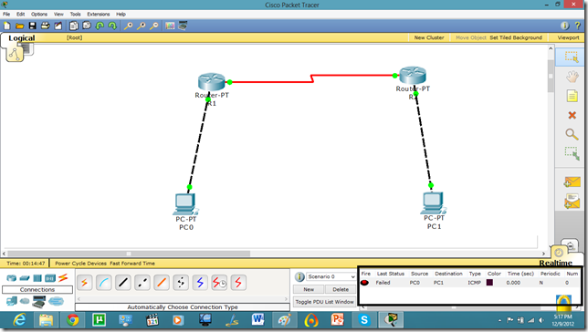
As we set the authentication on one router the communication is disabled.
 12

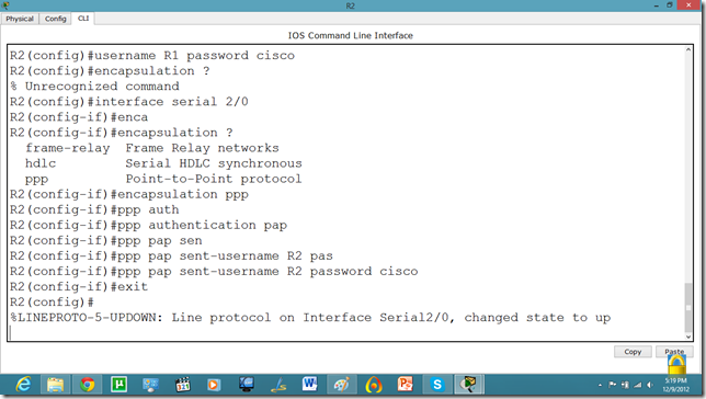
Let us set it on other router as well.
 13
Now, they can communicate.

 15

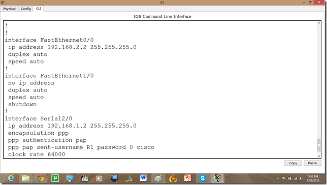
Now, if we run show run command in enable mode. We can see the authentication enabled in router.
 16


C program to Read From a File

#include <stdio.h> #include <stdlib.h> void main() {     FILE *fptr;     char filename[15];     char ch;   ...